
This DIY topic was submitted by local carpenter Bob Mullens. After you build a bench for yourself, think about building a second bench to donate to someone who could use one. Bob was kind enough to build a bench for the GNH Windham location after the Hurricane Irene flooding.
Download the full set of plans here.
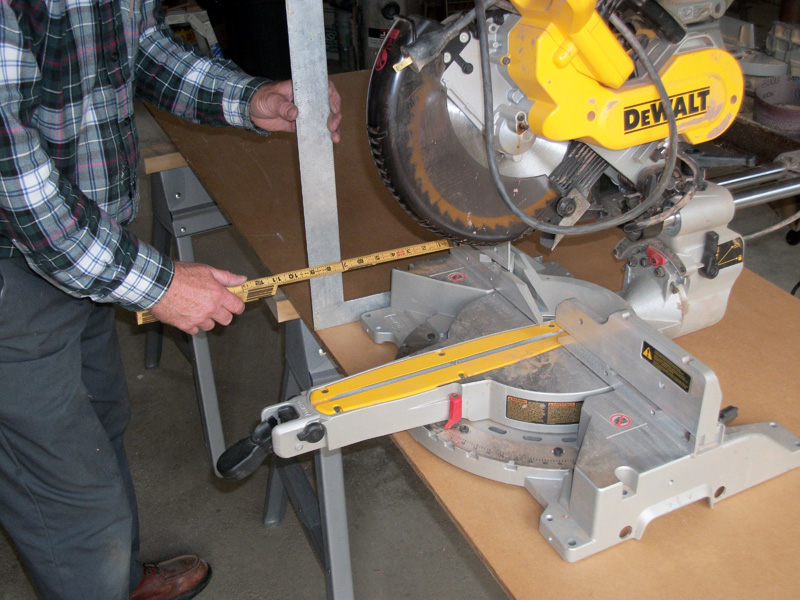
Determine the Width of the Base
1a. Place the miter saw on a sheet of plywood near the front edge. Using a framing square, measure (9) inches from the front edge of the plywood to the fence of the saw. Check to make sure that the front feet of the saw and other parts of the saw are at least (2) inches on the plywood. The arm of the saw should be sticking over the edge of the plywood. Measure (2) inches past the back feet of the saw or projecting brace which might be there. The width of the BASE is the distance from the front edge of the plywood to (2) inches past the back feet or projecting brace of the saw. Also, measure the distance from the front edge of the plywood to the front feet of the saw. When you position the saw in [4.d] and [5.a] you will use this number.
Building the Rails and Base
2a. Rip (2) strips of MDO plywood (3½) inches by (93) inches for the RAILS.
2b. Rip (2) strips of MDO plywood (2) inches wide and (93) inches long for the CLEATS.
2c. Using construction adhesive and (1) inch roofing nails, nail the (2) inch CLEAT to the (3½) RAIL, keeping the bottom edge even.
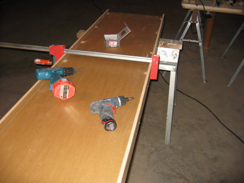
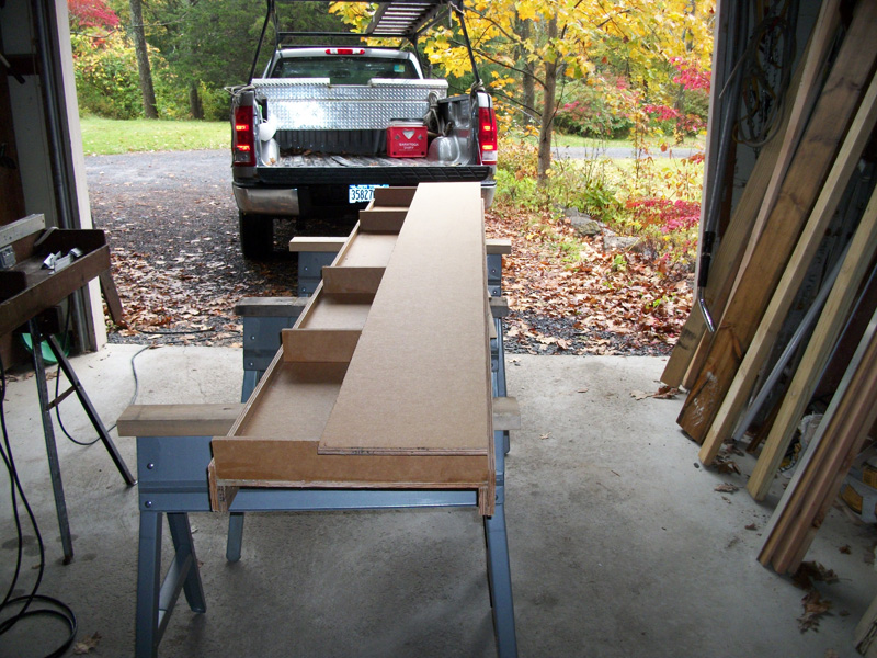
2d. Place a generous bead of construction adhesive along the inside edge of the two CLEATS. Place the BASE on top of the CLEATS and press into the construction adhesive. Clamp the two sides together with a bar clamp. Using a drill with a countersink, drill a series of holes through the BASE and into the CLEATS. Screw the BASE to the CLEATS using (1¼) inch flathead wood screws.
Note: Assemble the BASE and RAILS on a level surface to keep the bench from developing a sag. You might want to use three sawhorses.
Determine the Ribs of the Miter Saw Bench
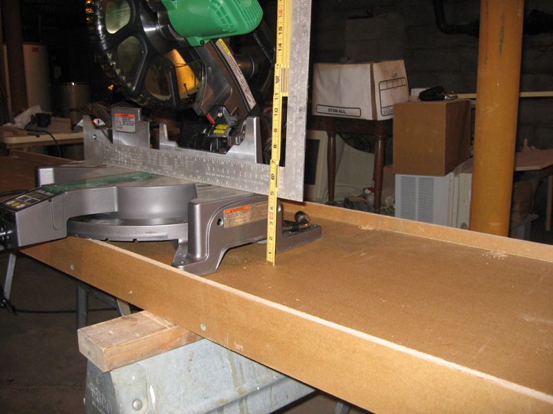
3a. Measure the height of your saw base and subtract (½) inch from the height. This is the height of the RIBS. Rip (2) strips of the RIB height off the remaining part of the MDO sheet.
Note: A RIB less than (3) inches will not allow electric boxes to be installed in them. You could rip the RIBS (3) inches and then build up the saw.
Assembling the Ribs
4a. Cut the RIB into (5) pieces the width of the BASE.
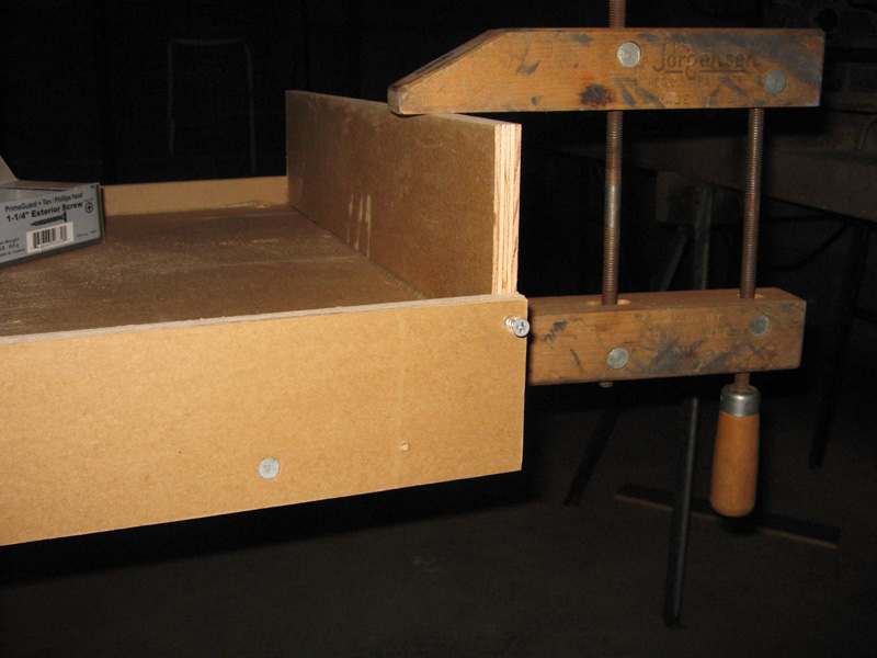
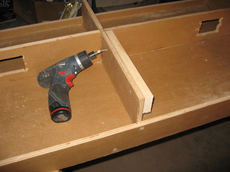
4b. On the right end of the BASE install the first RIB, using a bead of construction adhesive and (2) (1¼) inch flathead wood screws. Drill and countersink holes through the RAIL and into the RIB.
4c. From the first RIB, measure over (20) inches and install the second RIB. Square the second RIB with the base.Note: (20) inches is a good measurement for most saws; A large saw needs to be moved to the right. The center of the saw should be about (36) inches from the right side of the bench.
4d. Place your miter saw on the BASE, (3) inches to the left of the second RIB. The saw sits back from the front of the BASE the distance you measured in [1.a], the distance from the front edge of the plywood to the front feet of the saw. Place, but don’t fasten, the third RIB (3) inches from the left side of your miter saw. You will need at least (3) inches between the saw and the RIBS for your hand to move the wood that you will be cutting. Before you glue and screw this RIB, check the swing of the arm of the miter saw. If it is a compound miter saw, then tilt the saw to (45) degrees and swing the arm to see if the RIBS are in the right place. If your saw needs more space to work, then move the third RIB to the left.
Note: You might have to cut some of the front RAIL for the miter saw arm to swing smoothly.
4e. Install the forth RIB half way between the third RIB and the left end of the bench.
4f. Install the fifth RIB on the end of the bench.
Aligning the Miter Saw on the Base
5a. Place the miter saw between the second and third RIB of the BASE. Cut (4) pieces of (1x1x⅛) inch aluminum angle (4) inches long (or longer if the saw’s feet are wide. The aluminum angle should be (2) inches wider than the saw’s feet ) and place one of them under each leg of the miter saw base. Center the miter saw between the two RIBS, and the saw should be the [1.a] distance from the front of the BASE. Move the arm of the miter saw to be sure that it works properly.
Note: The (⅛) inch aluminum angle will keep the saw (⅛) inch above the DECK. This is done to keep the saw from binding.
5b. If the saw has a back extension, then cut a (5) inch piece of (1×1½x⅛) inch aluminum bar and slide it under the back extension.
Determine the Width of the Deck
6a. The DECK‘S width is the 9 inches from line [1.a] (or an adjustment that you had to make) plus the width of the FENCE which (is 1½”). Most likely yourDECK will measure (10½) inches. Rip the DECK‘s width from the MDO sheet.
Backing for the Three Electric Receptacles
7a. Remove the miter saw from its place on the bench and place the full length of the DECK on the top of the BASE, even with the front edge of the RIBS. Draw a line on the (5) RIBS where theDECK crosses them. From this line, measure (1) inch toward the front of the RIBS. Mark this line on the (5) RIBS.
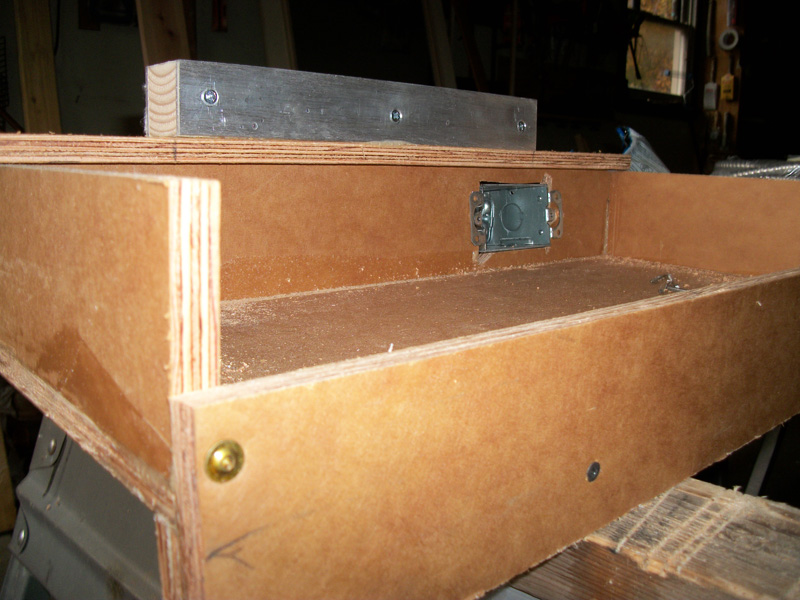
7b. Cut (3) pieces of RIB material to fit between the (5) RIBS. In the center of each piece, cut a hole for an electric box.
7c. Install the electric box backing using construction adhesive and screws. Install the backing in line with the front pencil mark on the ribs. When the DECK is placed on top of the RIBS, the electric backing will be (½) inch back from the edge of the DECK.
7d. Install (5) pieces of (1×2) pine from the front of the RIB to the electric box backing, even with the top of the RIB. These are the cleats for the DECKS.
Building the Decks and Fences
8a. Cut the DECK strip of MDO the length from the first RAIL to the second RAIL. And cut a second piece of the DECK strip the length of the third RAIL to the fifth RAIL.
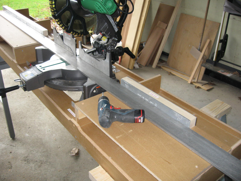
8b. Rip a (2x4x8), (1½) inches by (1¼) inches. This will be the FENCE. Place the miter saw in its place on the miter saw bench. Some compound miter saws have parts which slide past the base of the saw. If this is your case, then allow the parts to slide. You should also tilt the saw to (45). Cut the left fence the length of the left DECK or the length of the DECK minus any projection of the saw base.
8c. Cut the right FENCE (16) inches. The FENCE is not cut to the full 20 inches so the right end of the bench can be used with a router, where the FENCE might interfere with the tool.
8d. Install pieces of (1½ x ⅛) inch aluminum bar stock to both sides of theFENCES. The aluminum should be put on the (1¼) inch side of the FENCES. The FENCES should now measure (1½ x 1½) inches.
8e. Fasten the FENCES to the DECKS.
Drilling the Aluminum Angles
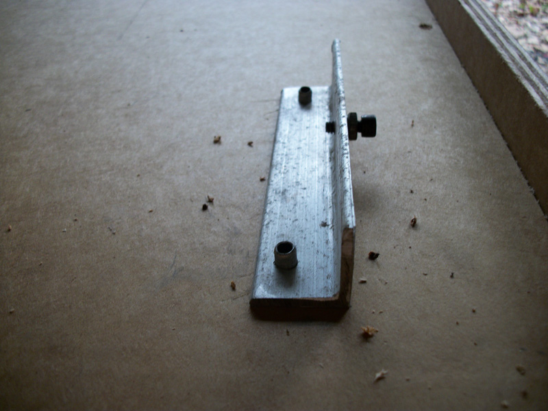
9a. Drill (2) #11 holes in four aluminum angles which go under the feet of the saw. Position the holes at the ends of the angles, so that the pop rivets will not interfere with the saw’s feet.
9b. Move the saw to the center of theBASE, place the front aluminum angles under the feet of the saw. Drill a (#25) hole through the aluminum angles and into the center of the front feet miter saw. Remove the angles and tap a #10-24 hole through the holes in the aluminum angles. Where the (#25) drill passed through the feet of the miter saw, drill (¼) inch holes. Through the #10-24 holes in the aluminum, screw a #10-24 x ½ inch Allen screw with a lock washer and a 10-24 nut. The screw should pass through the aluminum angle about (¼) inch. Tighten the 10-24 nut into the lock washer. The two Allen screws help to keep the saw in its holder.
Installing the Two Decks and the Saw
10a. Before you install the DECKS you should have a qualified electrician wire the electric boxes.
10b. You are going to fasten the saw to the BASE and the DECKS to the RIBS now. Set the miter saw in its place on the BASE, slide the aluminum angles under the saw’s feet. Place the short DECK on the right side of the bench and the longer DECK on the left side of the bench. Using a straight edge, line the miter saw up with the two DECKS. Keep the fronts of the DECKS even with the front corners of the RIBS. Pop rivet the aluminum angles where they meet the saw on the DECK. Pop rivet a (4) inch aluminum angle on each side of the front feet to keep the saw from moving side-to-side. Drill and countersink holes through the DECKS and into the cleats. Screw the DECKS into the cleats using (1¼) inch wood screws. Do not glue the DECKS to the cleats so you can access the electric boxes. If someday you have to re-align the saw, do it by moving the DECKS, not the saw in its holder.
How to Use the Miter Saw Bench
The miter saw and bench are to be used by responsible woodworkers, 18 years of age or older. The saw and bench are designed to cut wood moldings, shelving and framing lumber. This power tool and bench are inherently dangerous; using them could cause physical harm to the operator.
To set up the bench and miter saw
Place the saw horses on dry and level ground.
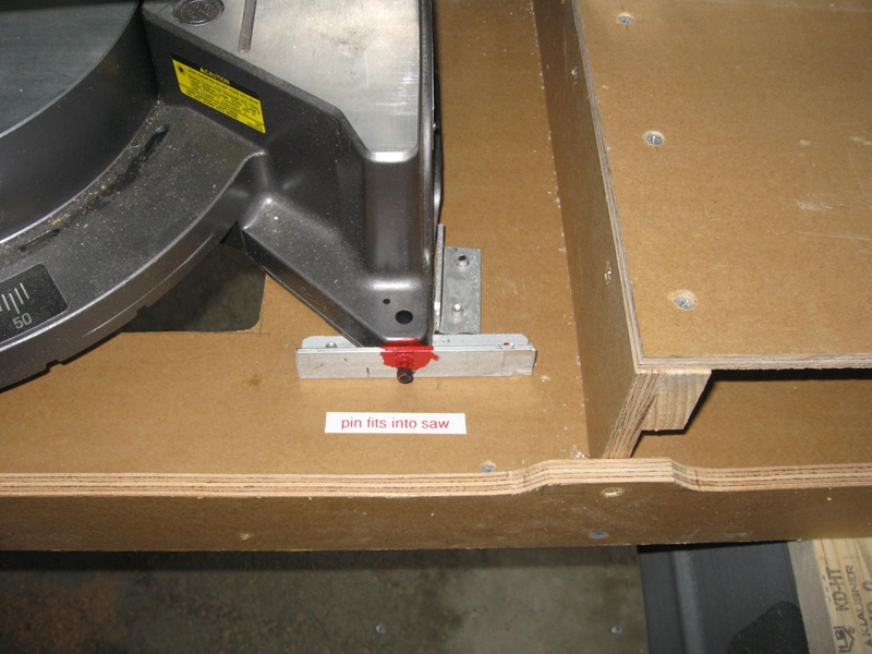
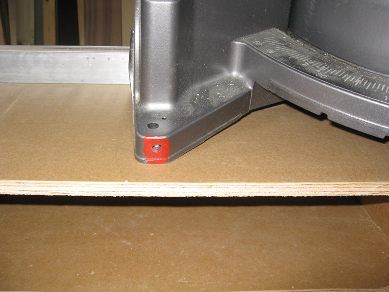
To place the saw in its holder, lift the saw and tilt the front legs of the saw into the pins coming through the 1×1 aluminum angle brackets.
Read and follow the directions which came with the saw.
Use safety glasses!